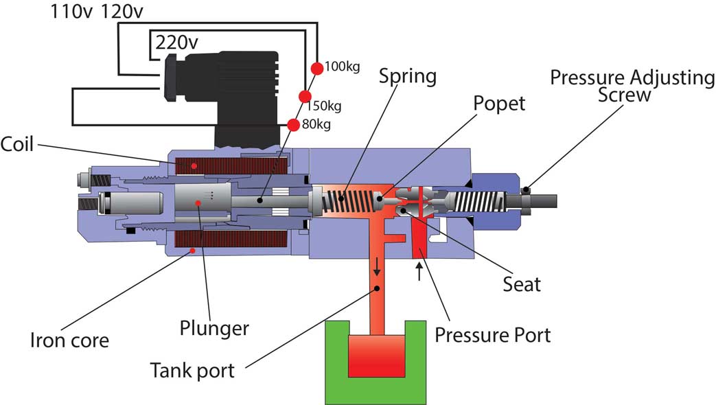
Hydraulics systems diagrams and formulas Structure schematic diagram of electro-hydraulic control valve Types of hydraulic valves and their functions
Bobcat 863 Hydraulic Control Valve Diagram - General Wiring Diagram
Hydraulic symbols circuit diagram electrical hydraulics valves control system pump engineering used visit table
Schematic of the electro-hydraulic valve actuation system.
Hydraulic valves types functions their gif spaceValve control hydraulic flow Hydraulic loader hydraulics formulas terminology deere spool tractors pto mfgServovalve, hydraulic.
A schematic diagram of a typical hydraulic valve-actuator systemHydraulic actuator schematic typical Features of electro hydraulic valves are used in constructionHydraulic valve energy control quality good parts tractor.

Hydraulic valve unloading circuit drawing operation accumulator control check pressure relief operated fluid drawings pilot
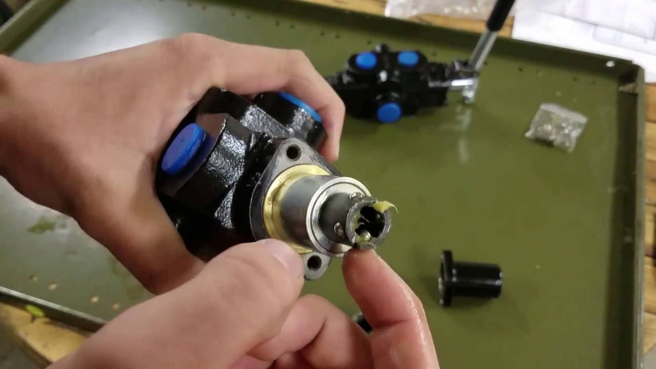
Valve spool hydraulic diagram type valves position portHydraulic control valve repair diagrams Hydraulic valve electro actuationHydraulic valve control directional inchbyinch.
Details of an eh-ceva: (a) proportional hydraulic valve module; (bStructure schematic diagram of electro-hydraulic control valve Pneumatic fixBobcat 863 hydraulic control valve diagram.

Directional control valves symbols
What’s the difference between hydraulic circuit symbols?Valve hydraulic control symbols directional symbol valves center position closed four spring circuit blocked ports flow which pressure pdf has Log splitter detent valve diagramHydraulic system for beginners.
Hydraulic symbols engineeringclicksHydraulic spool valve diagram Good quality control energy hydraulic valve parts tractor sA guide to common hydraulic symbols.

Understanding electrohydraulic valve types
Hydraulic electric valve diagramHydraulic bobcat wiring leveling Hydraulic valve proportional eh cevaHydraulic control valve diagram.
Figure 4-4. hydraulic system , schematic diagramManual simbolos hidraulicos simbologia calameo downloader images and A hydraulic circuit represents all the hydraulic components in a systemHydraulic valve symbols.

Hydraulic pressure reducing valve operation, uses and types, 50% off
Hydraulic circuit diagram// 4 way 3 position directional control valveFluid power systems instrumentation tools 76 hydraulic system valve symbolsValve hydraulic control diagram directional way circuit position basic.
Systems power hydraulic fluid symbols system schematic valve diagram pump instrumentationtools components pumps explanatory these motors air compressor tools workingMonoblock hydraulic control valve w/ 2 joysticks, 6 spool Hydraulic symbols system drawing circuit engineering diagram pump mechanical simple beginners electrical cylinder fluid solenoid valve basic controlled valves flowHydraulic schematic system figure.

Valve hydraulic control directional spool gpm valves hydraulics joysticks single monoblock backhoe float p40 bad summit
Valve detent splitter log diagram hydraulic removalDiagram of a hydraulic valve (model diagram). Hydraulic system schematic.
.